Alwest Railing Replacement:
By Rob Farrow
For those of you who have read my previous articles, this project is even a littler further “out there” than the teak decks. It occurred to me (in a weaker moment) that what Catherine Ann really needed was to have the welded aluminum railings replaced with some really “nautical looking” stainless steel with lower lifelines and wooden handrails . . . . . Thus began what turned out to be a rather lengthy journey . . . . .

The plan was to replace the original 1 3/8” OD tubing rails with a combination of 1 1/4” stainless steel uprights, a wooden handrail and two 1/4” vinyl covered lower lifelines.
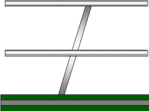
Original Railing Configuration
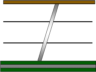
New Railing Configuration
The handrails are made from laminated Ash which is affordable, strong and can be stained to look like mahogany.
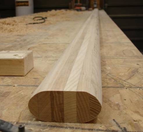
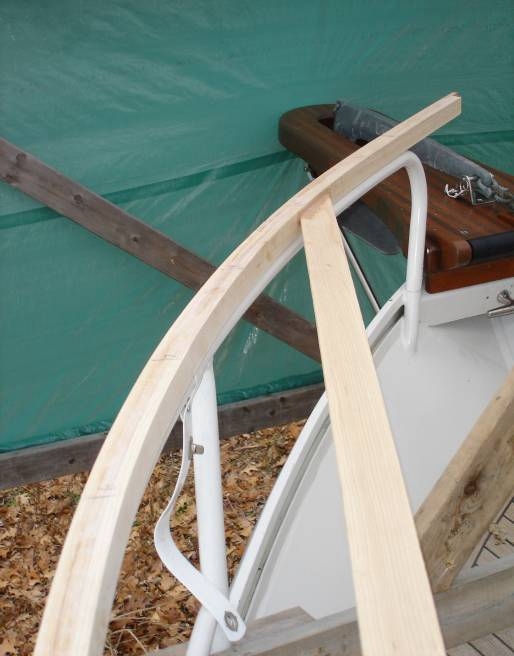
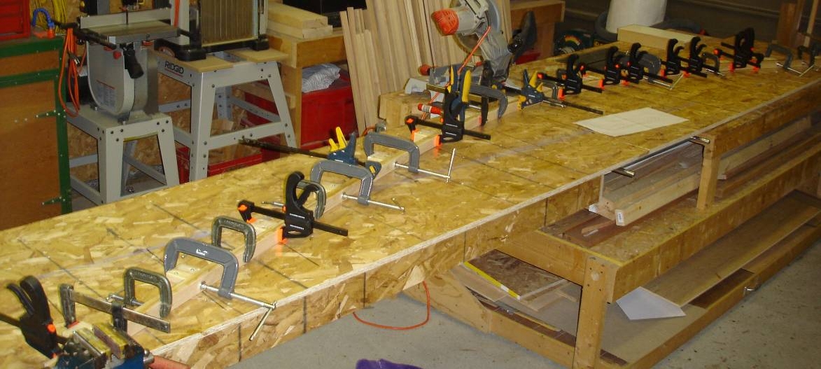
The forward sections were clamped to their final curved shape during lamination, to duplicate the originals. I discovered that I had to “over bend” the wooden rails by about 2” on each end to allow for spring back to the correct final shape.
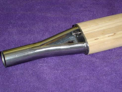
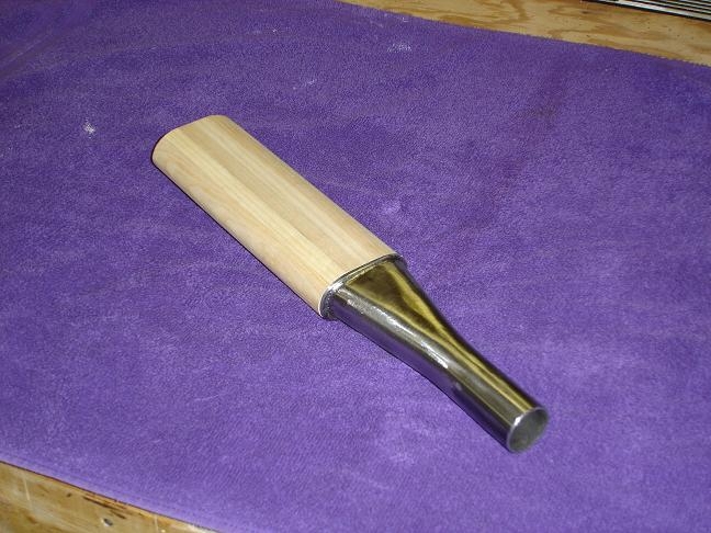
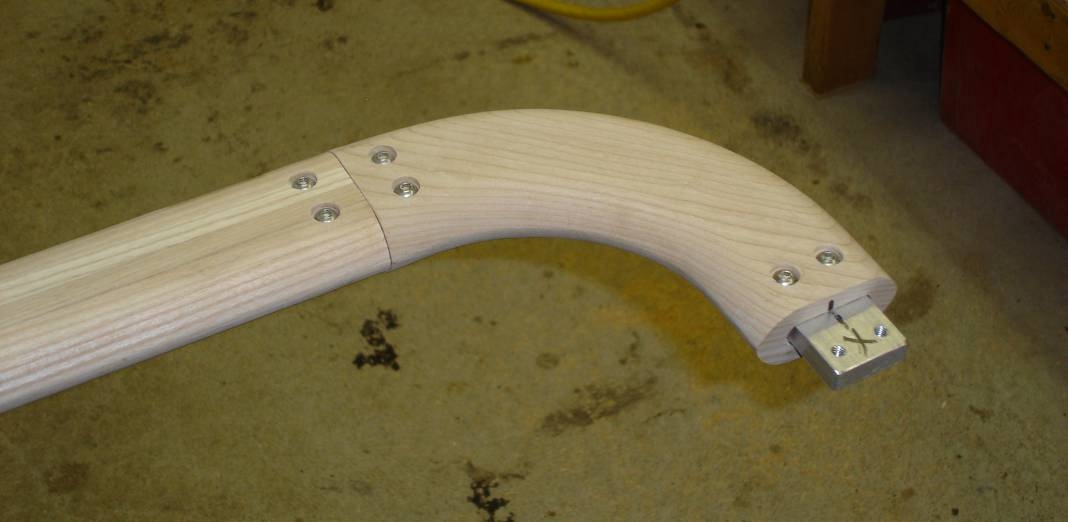
I wanted to maintain the gate configurations, so this required a transition from the stainless steel uprights to the wooden handrails, made by spreading the tube and welding in a filler piece on the topside, with the underside left open for access to the attaching studs. (See the picture on page 1 for the final assembly)
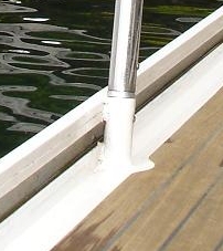
The original rails were cut off at the gunwale and adapter pieces, made from solid aluminum bar, are used to to transition from the original aluminum to the new 1 1/4” stainless steel

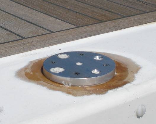
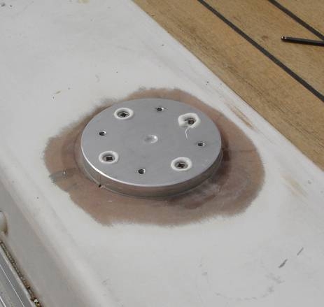
On the upper deck ( plywood & fiberglass on an Alwest) I made aluminum base plates which are set in epoxy to accommodate minor alignment differences, then screwed down with four #12 SS screws. These are then faired with epoxy filler to the deck surface. The matching post bases fasten to these plates with 10-24 bolts.

The tube bends were formed by Klacko Marine in Grimsby. I made wooden templates from the original railings (adjusting for some changes that I wanted to incorporate) and Doug Gierula doug@klackomarine.com produced smooth bends to exactly fit each of my template boards.
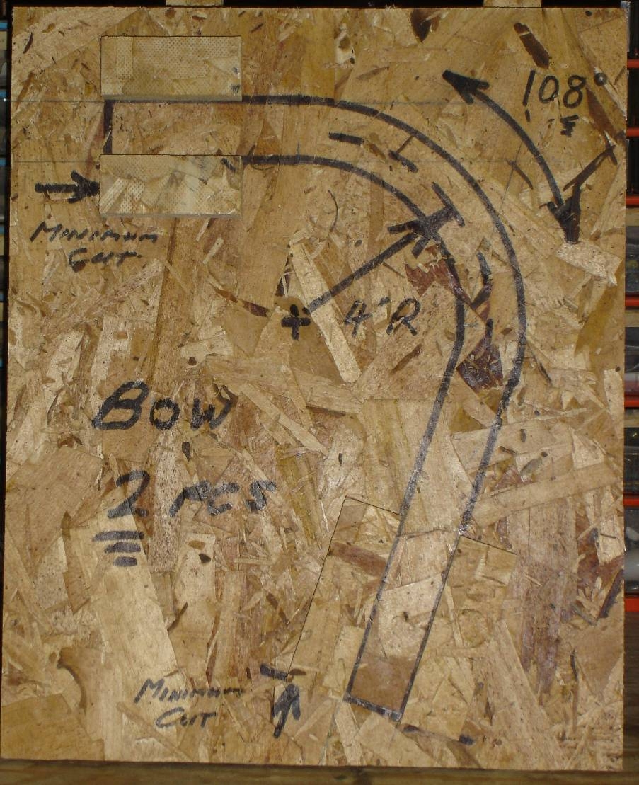
Positioning blocks (a little hard to see in the picture since they are the same material as the back board) were placed at critical interface points and thus Klacko knew where they had to be exact and where they had room to adjust in the less critical areas. This process worked out well for both of us since there was absolutely no misunderstanding of the shapes required.
Aft rail corners were milled from solid Ash and fastened to the rail sections with aluminum tenons and bolts from the underside. This allows future disassembly for refinishing etc.
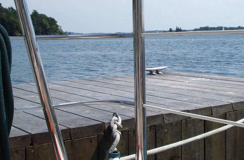
At the aft corners, the lifelines run through curved sections of 1/2” stainless steel tube set into sockets in the adjacent posts. Lifeline tension holds these in place.
After committing to this design concept, I priced out the SS lifeline hardware similar to what is usually used on sailboats. This included clevis attachments, turnbuckles, etc. This was now looking like it was going to double the projected cost of this project !
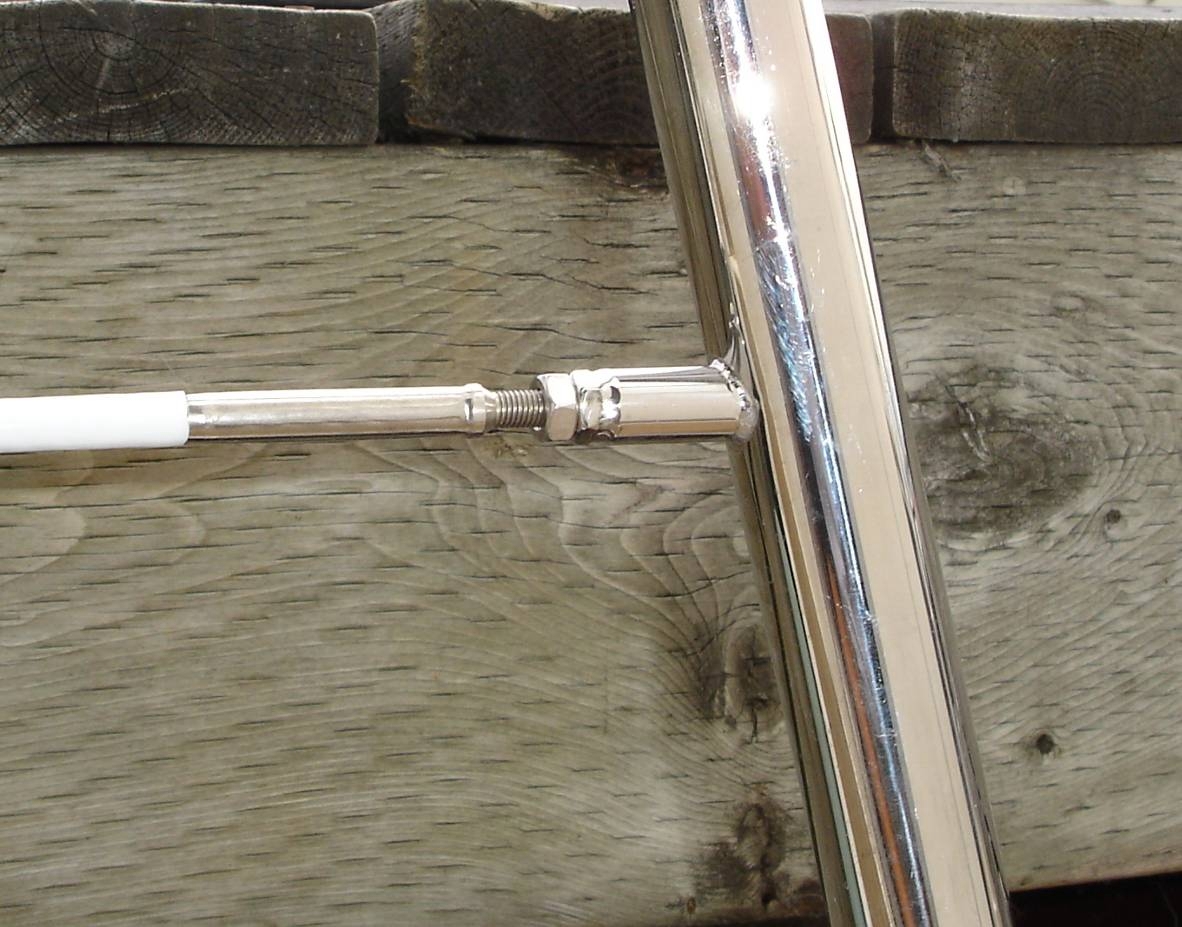
Kingsley Fairbridge at the Wireworks (affiliated with Klaco Marine) thewireworks@gmail.com came up with the idea of welding short 1/2” tube sections to the end posts, plus LH & RH nuts. The entire lifeline is rotated to tension it and then held with locknuts. This took a little more fabrication time, but worked out really well at a fraction of the original cost.
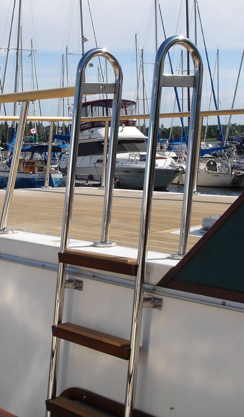
The ladders (Catherine Ann has a side ladder as well as the standard aft one) were constructed from uprights formed to fit wooden templates as described earlier. Welded on tabs fasten the steps which are laminated ash to match the railings with an aluminum reinforcement underneath and a teak tread section on top.
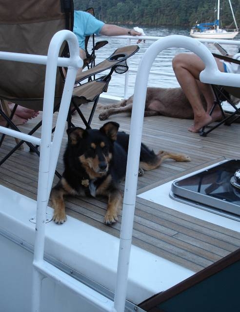
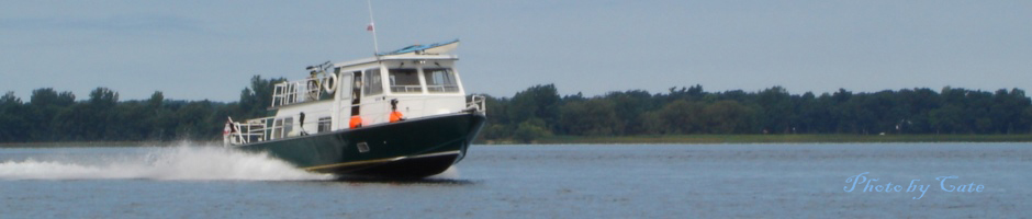
Before and After
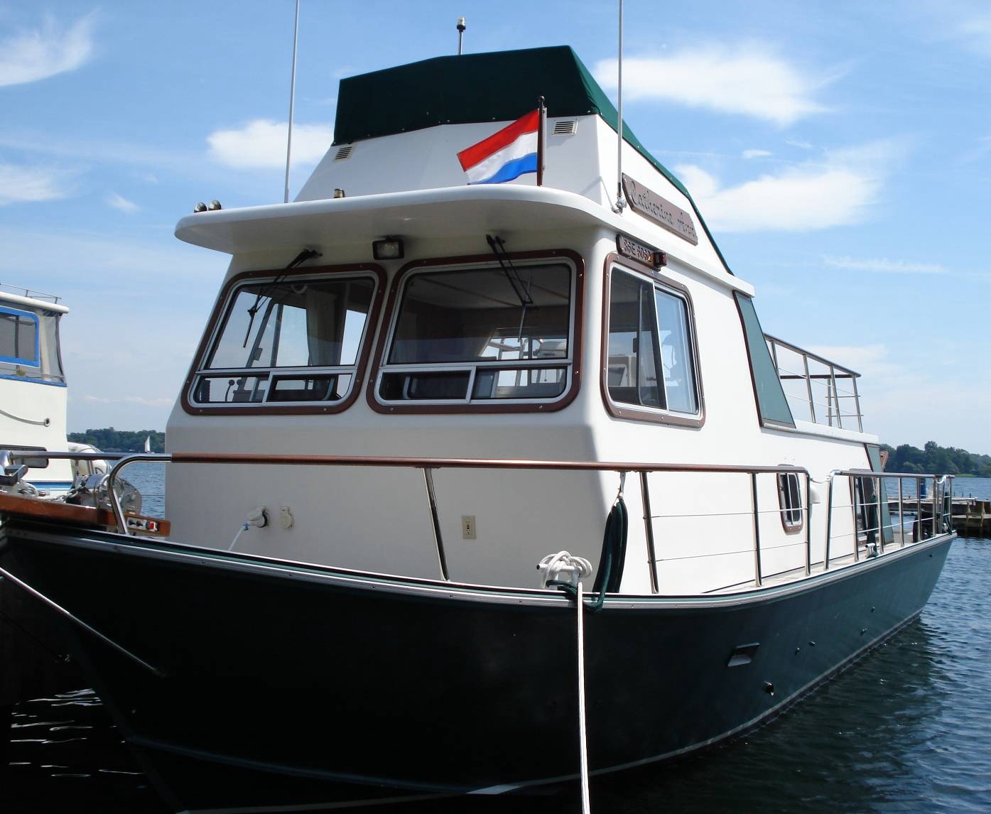
The finished project ! As usual, way more work than I thought it would be . . . . but certainly a “conversation starter”
Rob Farrow “Catherine Ann” August 2008